2B.2 Measurement of the core magnetization characteristic
2B.2.1 General
Measuring the core magnetization characteristic implies
– the measurement of the magnetizing inductance Lm;
– the measurement of the remanence factor KR;
– the determination of the error at limiting conditions using an indirect method.
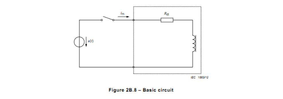
All of these are based on the following relationship. If an arbitrary voltage is applied to the secondary terminals (see Figure 2B.8), the flux linked through the secondary winding at time t is related to this voltage through the equation.
NOTE As the term “exciting current” is reserved for the r.m.s. value using a.c. quantities (see 3.3.207), and the term “magnetizing current” are used for instantaneous values in the d.c. method and capacitor discharge method.
The methods described in the following clauses take advantage of this relationship.
The effect of the voltage drop across the secondary winding resistance shall be estimated. If it exceeds 2 %, this drop shall be deduced from the voltage measured.
For TPX current transformers, it is necessary to demagnetize the core before each test, because of the high remanence factor. For TPY current transformers the remanent flux is often so low that it can be neglected. Demagnetization requires additional means by which the core can be subjected to slowly decreasing hysteresis loops starting from saturation. A direct current source will normally be provided when the d.c. test method has to be used.
Either of the three methods (a.c. method, d.c. method, capacitor discharge method) may be applied.
2B.2.2 A.C. method
2B.2.2.1 Determination of the magnetizing inductance Lm
A substantially sinusoidal a.c. voltage is applied to the secondary terminals and the corresponding value of the exciting current is measured. The test may be performed at reduced frequency f’ to avoid unacceptable voltage stressing of the winding and secondary terminals. Effects of undue eddy current losses in the core and capacitive currents between the winding layers will be less likely to cause false readings at lower frequencies. The result shall be shown as a saturation curve.
The exciting voltage shall be measured with an instrument whose response is proportional to the average of the rectified signal, but calibrated in r.m.s. The exciting current shall be measured using a peak reading instrument.
The peak value of the secondary linked flux may be derived from the measured r.m.s. value of the applied voltage U at the frequency f’.
Considering this equation, the curve gives the required relationship between the peak value of the exciting current and the peak value of the secondary linked flux. The magnetizing inductance Lm is defined as the mean slope of this curve between 20 % and 70 % of the saturation flux.
NOTE 202 This formula differs slightly from the formula given in the preceding standard IEC 60044-6 (B4) due to the improved definition of saturation.
2B.2.2.2 Determination of the error at limiting conditions
The test arrangement of 2B.2.2.1 shall be used.
NOTE For TPZ current transformers, the accuracy is specified only for the a.c. component while, in the determination of the permissible value during indirect tests, it is also necessary to take the d.c. component of the exciting current into account. In the above equation, the d.c. component is represented by (Ktd – 1).
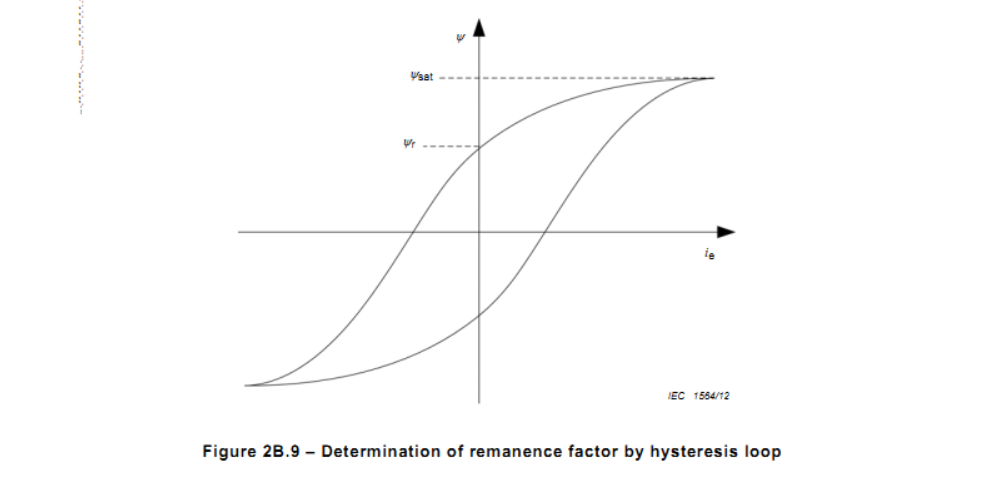
2B.2.2.3 Determination of the remanence factor KR
Other than in 2B.2.2.1 and 2B.2.2.2, the waveforms of the a.c. signals have to be detected.
In determining the remanence factor KR by the a.c. test method, it is necessary to integrate the exciting voltage according to equation (1) given in 2B.2.1. The integrated voltage with the corresponding current will display a hysteresis loop, showing the saturation flux. The secondary linked flux value at zero crossing of current is deemed to represent the remanent flux. See Figure 2B.9.
At lower frequencies, effects of undue eddy current losses in the core and capacitive currents between the winding layers will be less likely to cause false readings.
NOTE It shall be estimated as the secondary linked flux value where the curve is practically horizontal.