2B.2.3.3 Determination of the magnetizing inductance Lm
The test procedure of 2B.2.3.2 shall be used.
NOTE This formula differs slightly from the definition given in the preceding standard IEC 60044-6 (B4) due to the improved definition of saturation.
2B.2.3.4 Determination of the error at limiting conditions
The test circuit according to 2B.2.3.1 shall be used.
For determination of the error at limiting conditions, the magnetizing current at the secondary linked flux shall be measured while increasing the flux.
NOTE For TPZ current transformers, the accuracy is specified only for the a.c. component while, in the determination of the permissible value during indirect tests, it is also necessary to take the d.c. component of the exciting current into account. In the above equation, the d.c. component is represented by (Ktd – 1).
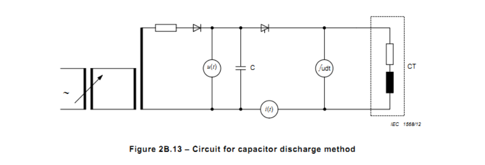
2B.2.4 Capacitor discharge method
The capacitor discharge method uses the charge of a capacitor for energizing the current transformer core from the secondary. The flux measurement is derived according to equation (1) given in 2B.2.1, where u(t) is the voltage across the terminals. See Figure 2B.13.
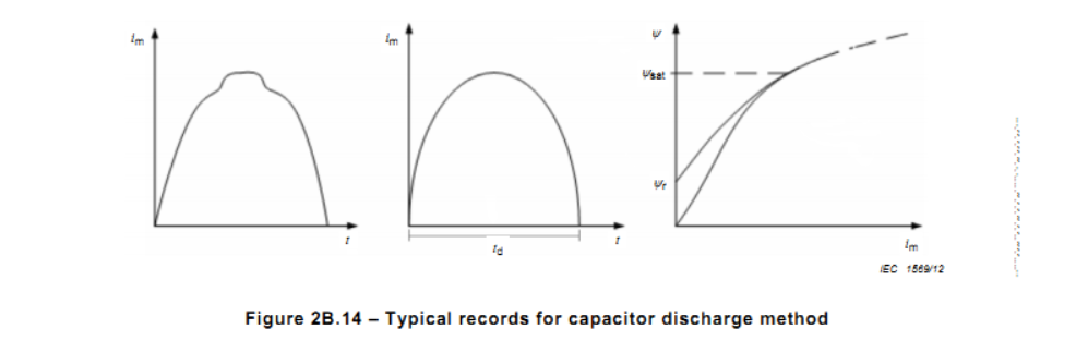
The capacitor is charged with a voltage sufficiently high to produce a secondary linked flux equal to or greater than the flux corresponding to Eal. See Figure 2B.13 and Figure 2B.14.
At the time when it is reached, the peak value of the secondary exciting current shall be measured and shall not exceed the peak value of the exciting secondary current Îal.
The secondary time constant Ts shall be determined by applying a voltage with a voltage-time integral corresponding to 90 % of Eal.
NOTE This definition of Ts does not conform with the definition in the above mentioned d.c. and a.c. methods.
In determining the remanence factor KR, the integrated voltage with the corresponding current will determine a hysteresis loop. If the exciting current has been such that the saturation flux is reached, the flux value at zero crossing of the current is deemed to represent the remanent flux.
2B.3 Direct test for determination of the error at limiting conditions
2B.3.1 General
The instantaneous error current can be measured in different ways. In all cases, the errors of the measuring system shall not exceed 10 % of the error limit corresponding to the class of the tested current transformer during the whole of the duty cycle.
2B.3.2 Direct test
Class TPX current transformers shall be demagnetized before the direct test because of the high remanence factor. It may be necessary to demagnetize class TPY current transformers if the remanence factor KR is not negligible.
Two direct tests shall be performed at rated frequency and with rated secondary burden:
a) The rated primary short-circuit current at rated frequency is applied without any offset. The a.c. component of the instantaneous error is measured and shall be in accordance with the theoretical value.
b) To verify that the current transformer meets the accuracy requirements of the specified duty cycle, the following test shall be performed:
The rated primary short-circuit current at rated frequency is applied with the required offset. For specified values of primary time constant up to 80 ms, the test is performed in the specified accuracy limiting condition (specified duty cycle). The primary time constant shall not deviate by more than 10 % from the specified value.


