2A.5 Direct test for composite error
The standard method is given by recording and digitizing the waveforms of the primary current and of the secondary current, and by calculating the composite error using numerical integration according to its definition in 3.4.203.
Nevertheless, in this annex, the traditional methods for the determination of the composite error with analogue instruments are described.
Figure 2A.4 shows a current transformer having a turns ratio of 1:1. It is connected to a source of primary (sinusoidal) current, a secondary burden with linear characteristics and to an ammeter in such a manner that both the primary and secondary currents pass through the ammeter but in opposite directions. In this manner, the resultant current through the ammeter will be equal to the exciting current under the prevailing conditions of sinusoidal primary current, and the r.m.s. value of that current related to the r.m.s. value of the primary current is the composite error according to 3.4.203, the relation being expressed as a percentage.
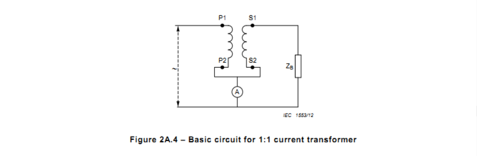
Figure 2A.4 therefore represents the basic circuit for the direct measurement of composite error.
Figure 2A.5 represents the basic circuit for the direct measurement of composite error for current transformers having rated transformation ratios differing from unity. It shows two current transformers of the same rated transformation ratio. The current transformer marked N is assumed to have negligible composite error under the prevailing conditions (minimum burden), while the current transformer under test and marked X is connected to its rated burden.
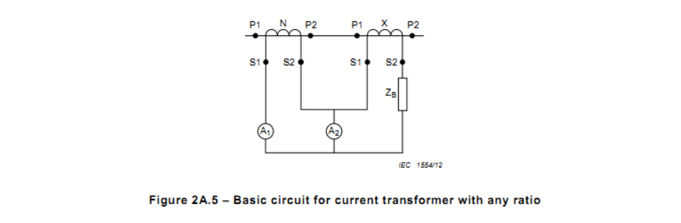
They are both fed from the same source of primary sinusoidal current, and an ammeter is connected to measure the difference between the two secondary currents. Under these conditions, the r.m.s. value of the current in the ammeter A2 related to the r.m.s. value of the current in ammeter A1 is the composite error of transformer X, the relation being expressed as a percentage.
With this method, it is necessary that the composite error of transformer N is truly negligible under the conditions of use. It is not sufficient that transformer N has a known composite error since, because of the highly complicated nature of composite error (distorted waveform), any composite error of the reference transformer N cannot be used to correct the test results.
2A.6 Alternative method for the direct measurement of composite errorAlternative means may be used for the measurement of composite error and one method is shown in Figure 2A.6.
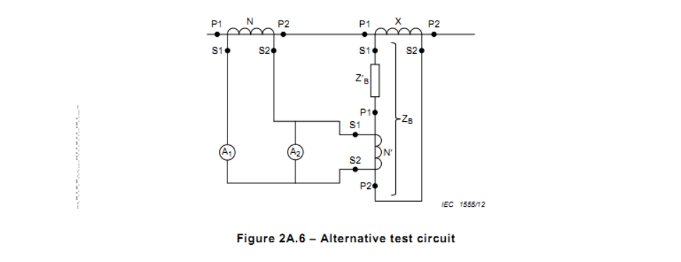
Whilst the method shown in Figure 2A.5 requires a “special” reference transformer N of the same rated transformation ratio as the transformer X and having negligible composite error at the accuracy limit primary current, the method shown in Figure 2A.6, enables standard reference current transformers N and N' to be used at or around their rated primary currents. It is still essential, however, for these reference transformers to have negligible composite errors but the requirement is easier to satisfy.
In Figure 2A.6, X is the transformer under test. N is a standard reference transformer with a rated primary current of the same order of magnitude as the rated accuracy limit primary current of transformer X (the current at which the test is to be made). N' is a standard reference transformer having a rated primary current of the order of magnitude of the secondary current corresponding to the rated accuracy limit primary current of transformer X. It should be noted that the transformer N' constitutes a part of the burden ZB of transformer X and must therefore be taken into account in determining the value of the burden ZB. A1 and A2 are two ammeters and care must be taken that A2 measures the difference between the secondary currents of transformers N and N'.
Under these conditions, the r.m.s. value of the current in ammeter A2, related to the current in ammeter A1, is the composite error of transformer X, the relation being expressed as a percentage.
NOTE When using the methods shown in Figure 2A.5 and Figure 2A.6, care should be taken to use a low impedance instrument for A2 since the voltage across this ammeter (divided by the ratio of transformer N' in the case of Figure 2A.6) constitutes part of the burden voltage of transformer X and tends to reduce the burden on this transformer. Similarly, this ammeter voltage increases the burden on transformer N.
2A.7 Use of composite error
The numeric value of the composite error will never be less than the vector sum of the ratio error and the phase displacement (the latter being expressed in centiradians).
Consequently, the composite error always indicates the highest possible value of ratio error or phase displacement.
The ratio error is of particular interest in the operation of overcurrent relays, and the phase displacement in the operation of phase sensitive relays (e.g. directional relays).
In the case of differential relays, it is the combination of the composite errors of the current transformers involved, which must be considered.
An additional advantage of a limitation of composite error is the resulting limitation of the harmonic content of the secondary current, which is necessary for the correct operation of certain types of relays.


